IPsec Site-to-Site VPN in pfSense - Tunnel Setup Guide
IPsec (Internet Protocol Security) is a standards-based protocol suite for establishing encrypted connections over public networks. Unlike proprietary VPN solutions, IPsec enjoys near-universal support across networking platforms: pfSense, Cisco ASA, FortiGate, MikroTik, Juniper, as well as cloud providers such as AWS, Azure, and GCP. This interoperability makes IPsec the primary choice for building site-to-site tunnels between locations running heterogeneous equipment.
This guide covers the complete lifecycle of an IPsec site-to-site VPN configuration in pfSense: from negotiating encryption parameters through to diagnosing connectivity issues. The material is intended for network engineers with prior firewall experience and a working understanding of VPN fundamentals.
IPsec Terminology
A solid grasp of the following terms and concepts is essential before proceeding with configuration.
IKE - Internet Key Exchange
IKE is the protocol responsible for negotiating security parameters and exchanging keying material. Two versions exist:
| Characteristic | IKEv1 | IKEv2 |
|---|---|---|
| Messages to establish | 6-9 (Main/Aggressive mode) | 4 |
| NAT-T support | Requires separate negotiation | Built-in |
| MOBIKE support | No | Yes |
| Reauthentication | Not available | Built-in |
| Compatibility | Broad (legacy devices) | Modern equipment |
Recommendation: unless compatibility with legacy equipment is required, IKEv2 should be used.
Security Association (SA)
An SA is a unidirectional logical connection between two endpoints that defines traffic protection parameters: encryption algorithm, hash algorithm, keying material, and lifetime. Bidirectional communication requires a pair of SAs - one for each direction.
Phase 1 - Control Channel
Phase 1 (IKE SA) establishes a secure control channel between two endpoints. During this phase, the following occurs:
- Mutual authentication (PSK or certificates)
- Negotiation of encryption and hash algorithms
- Diffie-Hellman key exchange
- Creation of the IKE SA with a defined lifetime
Phase 1 does not carry user traffic - it is exclusively a management channel for negotiating Phase 2 parameters.
Phase 2 - Data Channel
Phase 2 (Child SA / IPsec SA) defines which traffic is protected and how. The following parameters are negotiated:
- Source and destination subnets (Traffic Selectors)
- Encryption and hash algorithms for user traffic
- Encapsulation protocol (ESP or AH)
- PFS (Perfect Forward Secrecy) group
A single Phase 1 can service multiple Phase 2 entries - for instance, to carry traffic between different subnet pairs.
PSK and Certificates
Two primary authentication methods are available:
- Pre-Shared Key (PSK) - a shared secret string configured on both endpoints. Simple to set up but less secure: compromising the key on one endpoint exposes all tunnels using that key.
- X.509 Certificates - PKI-based authentication. Provides stronger identity verification, scales better across large numbers of tunnels, and allows individual certificate revocation without affecting other connections.
For site-to-site tunnels between two locations, PSK is generally sufficient provided the key is complex and at least 32 characters long. When connecting more than five sites, migrating to certificates is advisable.
Prerequisites
The following conditions must be met before beginning configuration.
Network Requirements
Static public IP addresses on both endpoints. If a static address is unavailable, Dynamic DNS (DynDNS) may be used, though tunnel stability will be reduced.
Non-overlapping subnets behind both endpoints. Policy-based IPsec cannot route traffic between identical subnets. Example of a valid configuration:
- Site A: LAN
10.1.0.0/24 - Site B: LAN
10.2.0.0/24
If subnets overlap, one side must be renumbered or NAT/BINAT must be configured in Phase 2.
- Site A: LAN
Agreed encryption parameters - both sides must support identical encryption algorithms, hash algorithms, and Diffie-Hellman groups.
Parameters to Agree with the Remote Side
The following parameters should be coordinated with the remote site administrator before configuration begins:
| Parameter | Example Value |
|---|---|
| Remote endpoint public IP | 203.0.113.10 |
| IKE version | IKEv2 |
| Authentication method | PSK |
| Pre-Shared Key | (complex key, 32+ characters) |
| Phase 1 encryption algorithm | AES-256-GCM |
| Phase 1 hash | SHA256 |
| DH Group | 14 (2048 bit) |
| Phase 1 lifetime | 28800 seconds |
| Local subnet | 10.1.0.0/24 |
| Remote subnet | 10.2.0.0/24 |
| Phase 2 encryption algorithm | AES-256-GCM |
| PFS Group | 14 (2048 bit) |
| Phase 2 lifetime | 3600 seconds |
Warning:
All Phase 1 and Phase 2 parameters must match on both endpoints. A mismatch in even a single parameter (for example, the DH Group) will prevent the tunnel from establishing.
Phase 1 Configuration
Phase 1 is configured under VPN > IPsec > Tunnels. To create a new tunnel, click the Add P1 button.
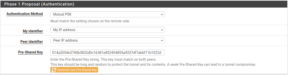
Fig. 1. Phase 1 configuration in the pfSense web interface
General Information
| Field | Value | Notes |
|---|---|---|
| Disabled | Unchecked | Clearing the checkbox activates the tunnel |
| Key Exchange version | IKEv2 | Recommended protocol version |
| Internet Protocol | IPv4 | Or IPv6, depending on WAN addressing |
| Interface | WAN | The interface through which the tunnel is established |
| Remote Gateway | 203.0.113.10 | IP address or FQDN of the remote endpoint |
| Description | Site B - Moscow Office | Label for tunnel identification |
When an FQDN is entered in the Remote Gateway field, pfSense will periodically perform DNS resolution, which is useful when the remote side has a dynamic IP address.
Phase 1 Proposal - Authentication
| Field | Value | Notes |
|---|---|---|
| Authentication Method | Mutual PSK | Pre-shared key authentication |
| My identifier | My IP Address | Automatically populated with the WAN IP address |
| Peer identifier | Peer IP Address | IP address of the remote endpoint |
| Pre-Shared Key | (your key) | Minimum 32 characters including letters, digits, and special characters |
Warning:
The PSK is case-sensitive. Verify that the keys match exactly on both endpoints, including spaces and special characters.
Phase 1 Proposal - Encryption Algorithm
Recommended parameters for modern deployments:
| Field | Value | Notes |
|---|---|---|
| Algorithm | AES-256-GCM | Authenticated encryption with hardware acceleration (AES-NI) |
| Key Length | 256 bits | Maximum key length |
| Hash | SHA256 | When using AES-GCM, hashing is handled by the built-in GHASH mechanism; however, the Hash field is used for the PRF (Pseudo-Random Function) |
| DH Group | 14 (2048 bit) | Minimum recommended group |
Multiple Encryption Algorithm entries may be added - pfSense and the remote endpoint will negotiate the strongest common option. However, for site-to-site tunnels it is advisable to specify exactly one parameter set, identical on both sides, to eliminate ambiguity.
Warning:
DES, 3DES, Blowfish, MD5, and SHA1 are considered deprecated and must not be used in new deployments. DH Groups 1, 2, 22, 23, and 24 do not provide adequate security.
Expiration and Replacement
| Field | Value | Notes |
|---|---|---|
| Life Time | 28800 | IKE SA lifetime in seconds (8 hours) |
| Rekey Time | (blank) | Automatically calculated at 90% of Life Time |
| Reauth Time | (blank) | Automatically calculated at 90% of Life Time |
| Rand Time | (blank) | Automatically calculated at 10% of Life Time |
The Rand Time value introduces random jitter into the rekeying schedule, preventing a situation where both endpoints simultaneously initiate rekeying.
Advanced Options
| Field | Value | Notes |
|---|---|---|
| Child SA Start Action | Default | Standard behavior |
| NAT Traversal | Auto | Automatic detection of NAT presence |
| MOBIKE | Disable | Not required for site-to-site with static IPs |
| Dead Peer Detection | Enabled | Detects remote endpoint unavailability |
| DPD Delay | 10 | Interval between DPD probes in seconds |
| DPD Max Failures | 5 | Number of missed responses before the peer is considered down |
With DPD enabled, pfSense will detect a remote endpoint failure in approximately 50-60 seconds (10 seconds * 5 attempts + overhead) and will re-establish the tunnel when connectivity is restored.
Phase 2 Configuration
After saving Phase 1, a Phase 2 entry must be added. Click Show Phase 2 Entries, then Add P2.
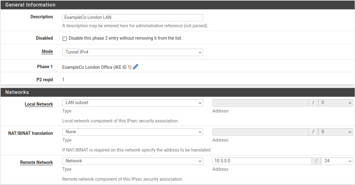
Fig. 2. Phase 2 configuration in the pfSense web interface
General Information
| Field | Value | Notes |
|---|---|---|
| Disabled | Unchecked | Phase 2 is active |
| Mode | Tunnel IPv4 | Standard mode for site-to-site |
| Local Network | LAN subnet | Or specify a subnet manually: 10.1.0.0/24 |
| NAT/BINAT | None | No address translation (when subnets do not overlap) |
| Remote Network | Network / 10.2.0.0/24 | Subnet behind the remote endpoint |
| Description | LAN Site A to LAN Site B | Phase 2 description |
If traffic between multiple subnet pairs (for example, LAN and DMZ) needs protection, a separate Phase 2 entry must be created for each pair.
Phase 2 Proposal - SA/Key Exchange
| Field | Value | Notes |
|---|---|---|
| Protocol | ESP | Encrypts and authenticates traffic |
| Encryption Algorithms | AES-256-GCM | Must match the remote side |
| Hash Algorithms | SHA256 | Not used for encryption with AES-GCM, but required by some implementations |
| PFS key group | 14 (2048 bit) | Perfect Forward Secrecy - generates fresh keying material at each rekeying |
PFS ensures cryptographic independence of session keys: compromise of one key does not allow decryption of traffic from previous or subsequent sessions.
Warning:
The AH (Authentication Header) protocol provides authentication only, without encryption. ESP should be used in the vast majority of scenarios.
Expiration and Replacement
| Field | Value | Notes |
|---|---|---|
| Life Time | 3600 | Child SA lifetime in seconds (1 hour) |
| Rekey Time | (blank) | Automatically calculated |
| Rand Time | (blank) | Automatically calculated |
The Phase 2 lifetime must be shorter than the Phase 1 lifetime. The standard ratio is Phase 1: 28800 seconds, Phase 2: 3600 seconds.
Keep Alive
| Field | Value | Notes |
|---|---|---|
| Automatically ping host | 10.2.0.1 | IP address of a host in the remote subnet to keep the tunnel active |
The automatic ping prevents tunnel teardown during periods of no user traffic. The default gateway of the remote subnet or another permanently reachable host is recommended as the target address.
Firewall Rules for IPsec
After configuring the tunnel, firewall rules must be created to permit traffic flow. Rules are needed on two tabs: WAN and IPsec.
WAN Interface Rules
The following traffic must be permitted through the WAN interface for the IPsec tunnel to establish:
| Protocol | Port | Purpose |
|---|---|---|
| UDP | 500 | IKE - key exchange |
| UDP | 4500 | NAT-T - NAT traversal |
| ESP | Protocol 50 | Encrypted traffic encapsulation (when NAT is not present) |
If the WAN interface has a default rule permitting all outbound traffic and inbound connections are initiated only by the remote side, additional WAN rules may not be necessary - pfSense automatically permits inbound IKE traffic for configured IPsec tunnels.
Warning:
When NAT-T (UDP 4500) is in use, the ESP protocol is encapsulated within UDP packets. In this case, a separate rule for ESP (protocol 50) is not required.
IPsec Tab Rules
The Firewall > Rules > IPsec tab governs traffic traversing all established IPsec tunnels. By default, this tab is empty - all tunnel traffic is blocked.

Fig. 4. Firewall rules on the IPsec tab
Minimum ruleset to permit traffic between sites:
| Action | Protocol | Source | Destination | Description |
|---|---|---|---|---|
| Pass | Any | 10.2.0.0/24 | 10.1.0.0/24 | Allow traffic from remote subnet to local |
| Pass | Any | 10.1.0.0/24 | 10.2.0.0/24 | Allow traffic from local subnet to remote |
In production environments, restricting rules to specific protocols and ports rather than using Any is recommended. For example, permit only ICMP, SSH (TCP 22), and HTTPS (TCP 443).
A detailed discussion of firewall rule principles is available in the pfSense Firewall Rules section.
Verifying the Connection
After saving the configuration and applying changes, the tunnel status should be verified.
Status > IPsec
Navigate to Status > IPsec to view the status of all IPsec tunnels.
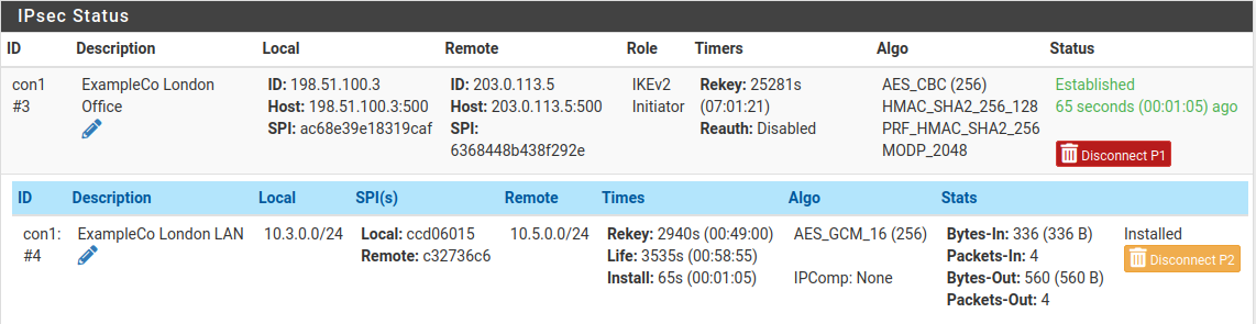
Fig. 3. IPsec tunnel status page
The page displays:
- Phase 1 - IKE SA status (Established / Connecting / Disconnected)
- Phase 2 - Child SA status with Traffic Selectors (local and remote subnets)
- SPI - Security Parameter Index for each SA
- Bytes In/Out - volume of transferred traffic
- Status - current state with Connect / Disconnect buttons
A successfully established tunnel shows Established status for Phase 1 and active Child SAs for Phase 2.
Command-Line Diagnostics
For more detailed diagnostics, the following commands are available via Diagnostics > Command Prompt or SSH:
# Status of all IPsec SAs
ipsec statusall

# Detailed status with traffic counters
ipsec status

# Restart IPsec service
ipsec restart

# View IPsec-related logs in real time
clog -f /var/log/ipsec.log

# Ping through the tunnel (from pfSense shell)
ping -S 10.1.0.1 10.2.0.1
The ipsec statusall command displays comprehensive information about all SAs, including negotiated algorithms, time until expiration, and byte counters.
Verifying Traffic Flow
After the tunnel has been established, the following checks are recommended:
- Ping between subnets - from host
10.1.0.100, runping 10.2.0.100 - Verify routing -
traceroute 10.2.0.100should show a direct route through the tunnel (no intermediate hops) - Check counters - in Status > IPsec, the Bytes In/Out values should increment as traffic flows
Connecting to Third-Party Equipment
IPsec is a standardized protocol, but implementations on different platforms have variations that can cause parameter negotiation failures.
General Recommendations
Pin a single parameter set - do not rely on automatic negotiation. Specify identical encryption algorithms, hash algorithms, and DH groups on both sides.
Use IKEv2 - when supported by both sides. IKEv2 eliminates many IKEv1 compatibility issues.
Verify identifiers - some platforms default to FQDN or Distinguished Name rather than IP address as the identifier. Identifier mismatch is a frequent cause of Phase 1 failure.
Align lifetimes - differing Lifetime values between platforms can create a situation where one side attempts rekeying while the other still considers the SA valid.
Cisco ASA
- Cisco ASA defaults to IKEv1 with Aggressive Mode for dynamic peers. When connecting to pfSense, explicitly configuring Main Mode or migrating to IKEv2 is recommended.
- The Phase 1 identifier on ASA is set with
crypto isakmp identity address- ensure pfSense is configured withPeer IP Address. - ASA supports a limited set of DH groups - verify compatibility before configuring.
FortiGate
- FortiGate supports both policy-based and route-based VPN. When connecting to pfSense in policy-based mode, Traffic Selectors (Phase 2 subnets) must match exactly.
- FortiGate uses its own algorithm naming:
aes256gcmcorresponds to AES-256-GCM in pfSense. - By default, FortiGate enables DPD in
on-demandmode - pfSense sends DPD probes at regular intervals. This does not cause issues but should be considered when analyzing logs.
MikroTik RouterOS
- MikroTik uses the terms
peerandpolicyinstead of Phase 1 and Phase 2. Thepeerparameters correspond to Phase 1,policyparameters to Phase 2. - In RouterOS,
enc-algorithmsandhash-algorithmmust be specified explicitly in the proposal section - automatic negotiation may select an undesirable algorithm. - MikroTik does not enable PFS by default - the
pfs-groupparameter must be set explicitly if PFS is in use on the pfSense side.
AWS Virtual Private Gateway (VGW)
- AWS VGW supports IKEv1 and IKEv2. When creating a VPN Connection, AWS provides a configuration file with recommended parameters.
- AWS uses two tunnels for redundancy - two Phase 1 + Phase 2 entries must be created in pfSense, one for each AWS public IP address.
- Phase 1 lifetime on the AWS side is 28800 seconds, Phase 2 is 3600 seconds. These values should be used in pfSense.
- AWS does not support AES-GCM in certain regions - consult the documentation for the specific region.
Azure VPN Gateway
- Azure VPN Gateway supports IKEv2 with both policy-based and route-based configurations.
- For connecting pfSense to Azure, a route-based VPN Gateway with VTI configuration on the pfSense side is recommended.
- Azure publishes a list of supported cryptographic parameters in its documentation - pfSense parameters must fall within this list.
- BGP over IPsec is supported only with a route-based VPN Gateway and VTI on the pfSense side.
Routed IPsec (VTI)
The configuration described above uses policy-based IPsec, where traffic is directed into the tunnel based on matching Traffic Selectors (Phase 2 subnets). An alternative approach is routed IPsec using Virtual Tunnel Interfaces (VTI).
How It Works
With VTI, pfSense creates a virtual network interface (ipsecX) that functions as a standard operating system interface. Traffic is directed into the tunnel via the routing table rather than the Security Policy Database.
Advantages of VTI over Policy-Based
| Characteristic | Policy-based | Routed (VTI) |
|---|---|---|
| Routing | Traffic Selectors | OS routing table |
| Dynamic routing | Not supported | BGP, OSPF via FRR package |
| Traffic monitoring | Limited | Full (tcpdump, traffic graphs) |
| Policy routing | Not supported | Supported |
| Phase 2 entries | One per subnet pair | One per address family |
| Failover | Manual | Gateway Groups |
When to Use VTI
Routed IPsec is recommended in the following scenarios:
- Dynamic routing (BGP/OSPF) through the tunnel is required
- The number of subnets on the remote side is large or changes frequently
- Integration with Gateway Groups for failover is needed
- Policy routing through the VPN tunnel is required
VTI Configuration
VTI configuration differs from policy-based in the Phase 2 settings:
- In Phase 2, set Mode to Routed (VTI)
- In the Local Network field, enter the local IP address of the tunnel interface (for example,
10.255.0.1/30) - In the Remote Network field, enter the remote IP address of the tunnel interface (for example,
10.255.0.2/30) - After saving, navigate to Interfaces > Assignments and assign the
ipsecXinterface - Enable the assigned interface and configure static routes or FRR as needed
Warning:
Both endpoints must support VTI mode for this configuration to function. When connecting to a device that does not support VTI, use policy-based IPsec instead.
Troubleshooting
Phase 1 Fails to Establish
Symptoms: Phase 1 status shows Connecting; logs contain NO_PROPOSAL_CHOSEN or AUTHENTICATION_FAILED messages.
| Issue | Cause | Resolution |
|---|---|---|
NO_PROPOSAL_CHOSEN | Encryption parameter mismatch | Verify that the algorithm, hash, and DH Group are identical on both sides |
AUTHENTICATION_FAILED | PSK or identifier mismatch | Check the PSK (case, spaces) and My/Peer identifier settings |
PEER_AUTH_FAILED | Certificate verification failure | Ensure the CA certificate is imported and has not expired |
| Timeout with no messages | UDP 500/4500 blocked | Check firewall rules on WAN and intermediate devices |
Phase 2 Fails to Establish
Symptoms: Phase 1 shows Established but Phase 2 does not appear or displays a no child SA status.
| Issue | Cause | Resolution |
|---|---|---|
NO_PROPOSAL_CHOSEN | Phase 2 encryption parameter mismatch | Verify the algorithm, hash, and PFS Group |
TS_UNACCEPTABLE | Traffic Selector mismatch | Ensure Phase 2 subnets are mirrored: the local subnet on one endpoint must equal the remote subnet on the other |
INVALID_KE_PAYLOAD | DH Group mismatch for PFS | Set an identical PFS Group or disable PFS on both sides |
Tunnel Established but Traffic Does Not Flow
| Issue | Cause | Resolution |
|---|---|---|
| No ping response | Missing rules on the IPsec tab | Create rules permitting traffic between subnets |
| One-way traffic | Rules created in one direction only | Add rules for both directions |
| Packets sent, replies not received | Asymmetric routing | Check the routing table on both endpoints |
| MTU issues | Fragmentation due to IPsec overhead | Reduce MSS via System > Advanced > Firewall & NAT (MSS Clamping) or adjust interface MTU |
DPD and Intermittent Disconnections
- Frequent DPD timeouts on an otherwise stable link may indicate remote endpoint overload or UDP packet loss. Increase DPD Delay to 30 seconds and Max Failures to 10.
- Tunnel does not recover after disconnection: check the Child SA Start Action parameter - the
Startvalue ensures automatic reconnection. - Simultaneous rekeying by both endpoints can result in duplicate SAs. Verify that Rand Time is not set to zero.
NAT-T and Double NAT
When NAT exists between IPsec tunnel endpoints:
- Ensure NAT Traversal is set to
AutoorForce. - With double NAT (NAT on both sides), port forwarding of UDP 500 and 4500 may be required on both routers.
- NAT-T encapsulates ESP within UDP 4500 - verify that this port is not blocked by intermediate devices.
Useful Diagnostic Commands
# View IKE SA details
ipsec statusall

# View routing table
netstat -rn

# Capture IPsec traffic on WAN
tcpdump -ni em0 esp or udp port 500 or udp port 4500

# Check for IPsec-related kernel messages
dmesg | grep -i ipsec

# View strongSwan logs
cat /var/log/ipsec.log | tail -100
Related Sections
- pfSense Firewall Rules - principles of creating and managing firewall rules, essential for proper IPsec tunnel operation
- pfSense Firewall Aliases - using aliases to simplify IP address and subnet management in IPsec rules
- NAT in pfSense - NAT configuration, including the interaction between NAT and IPsec