OPNsense as NAT instance
After creating the virtual machine, the next step is to configure SSH, which will be used to access the OPNsense web interface.
- To connect via SSH, enter the following command in the terminal:
ssh freebsd@public_vm_public_ip- Once connected, run the following command to gain administrative privileges:
ssh sudo suThen press the number “8” to enter the shell.
After these steps, the file with the new password will be available at the following path:
/conf/root_password Use this password to log in to the web interface at:
https://public-ip-vm
Username: root
Password: from file.
- After successful login, proceed with the basic configuration. First, ensure that the firewall is configured to allow HTTP and HTTPS traffic on the WAN interface (see Figure 1).
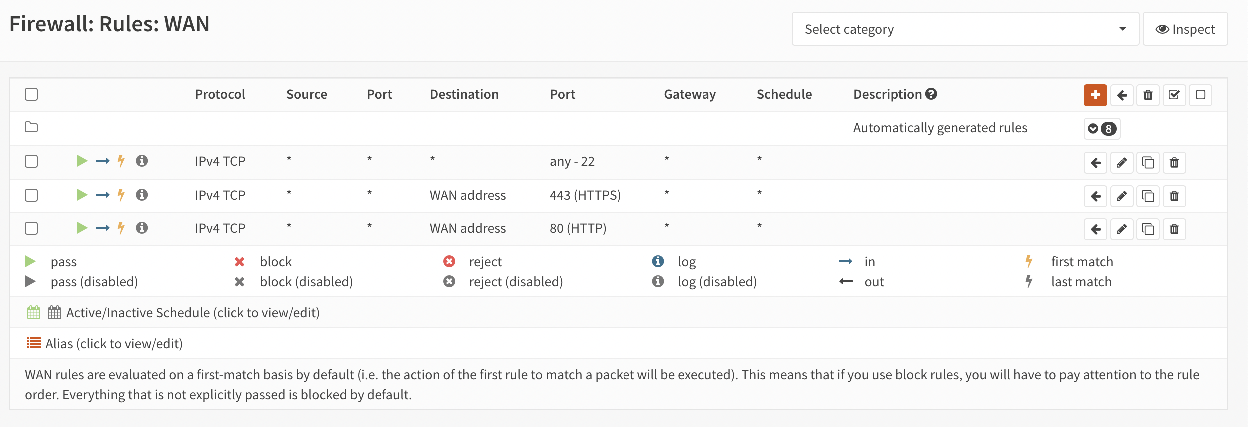
Figure 1. Configuring Firewall Rules
In the left panel, select “System → Wizard” (see Figure 2).
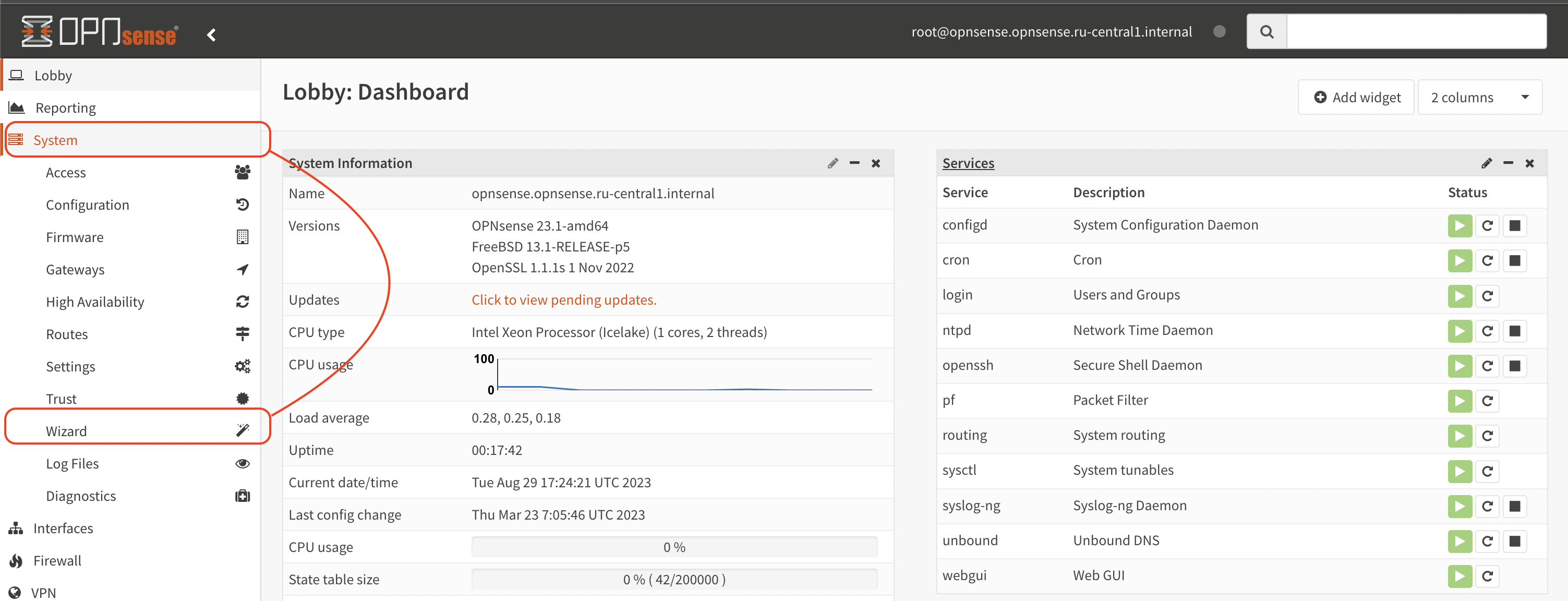
Figure 2. Starting the Wizard
These steps initiate the General Setup process (see Figure 3).
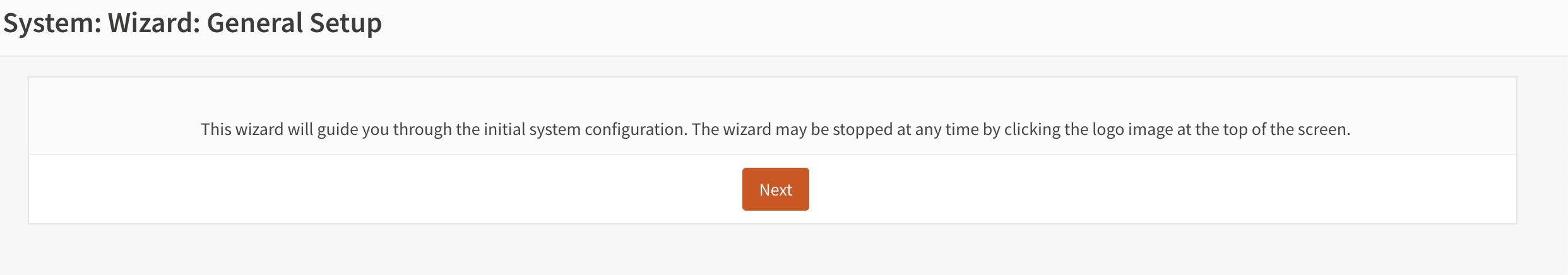
Figure 3. General Setup
- Click the Next button and set the parameters on the screen (see Table 1).
| Name | Value |
|---|---|
| Hostname: | You can leave the current name, as it will be taken from the cloud metadata when deployed and will match the virtual machine name |
| Domain: | You can also leave it as is |
| Language: | Choose whichever one you prefer |
| Primary DNS Server: | Primary DNS |
| Secondary DNS Server: | Optional |
| Override DNS: | [x]Allow DNS servers to be overridden by DHCP/PPP on WAN |
Table 1. Main Parameters
The rest of the settings can be left to the user’s preference (see Figure 4).
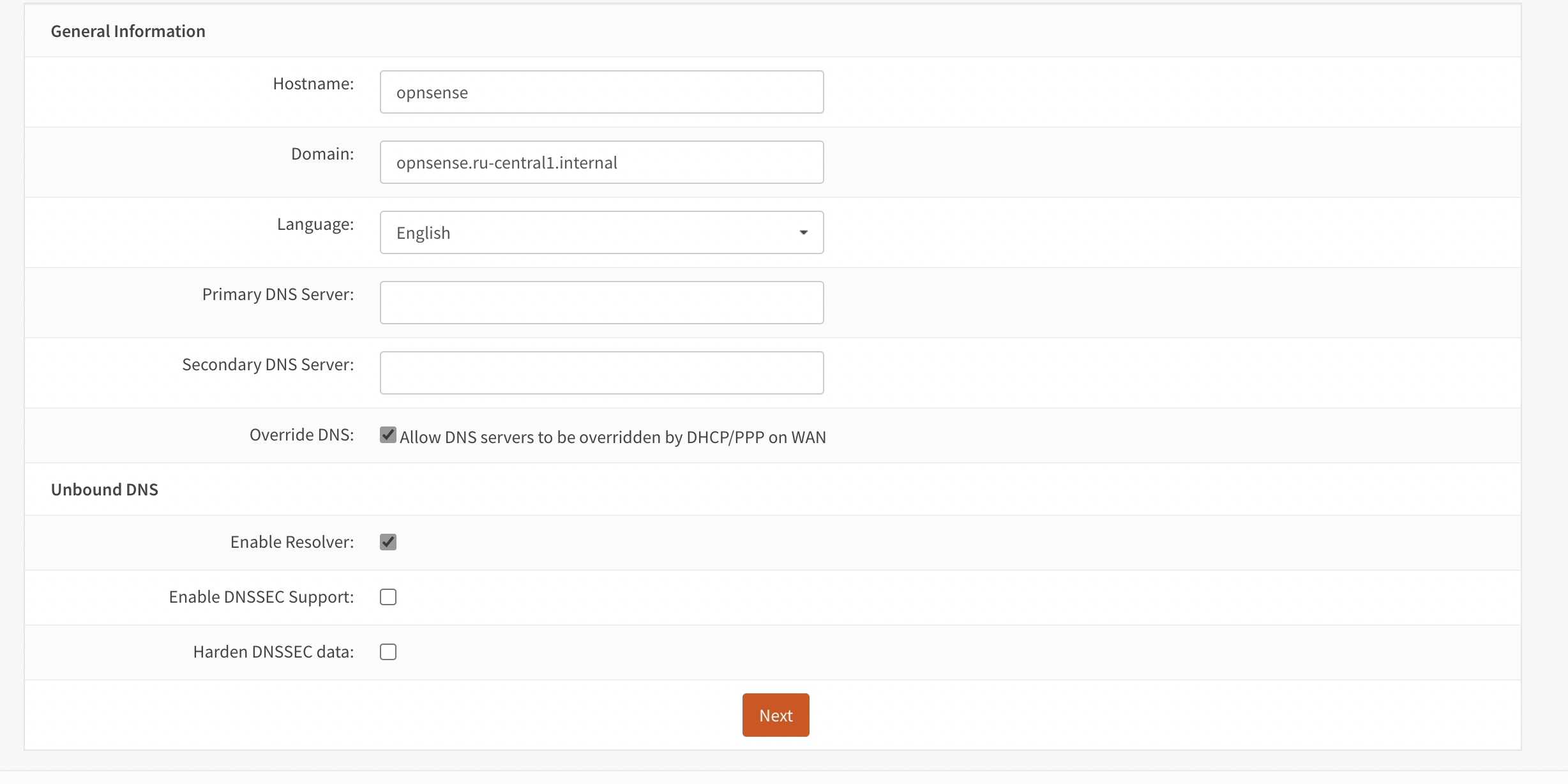
Figure 4. Main parameters
The next step is to click the “Next” button.
- Choose the appropriate time zone (see Figure 5).
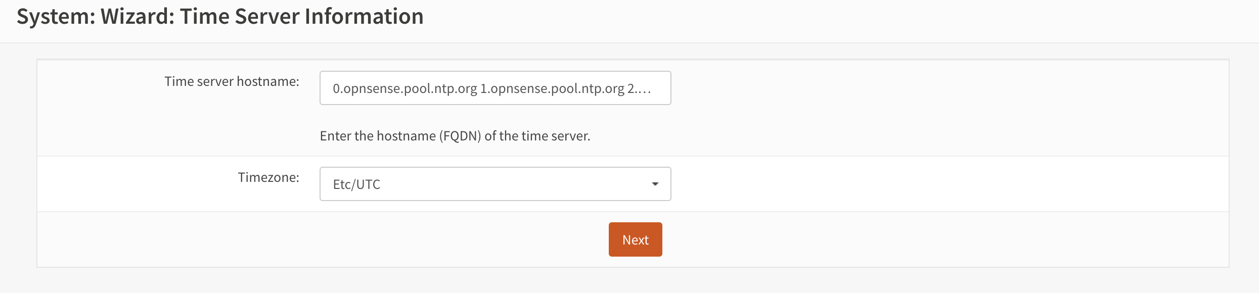
Figure 5. Configure the time zone
- The next step is to configure the WAN interface. In this example, the user can leave all settings unchanged, as DHCP is being used and no additional configuration is necessary (see Figure 6).
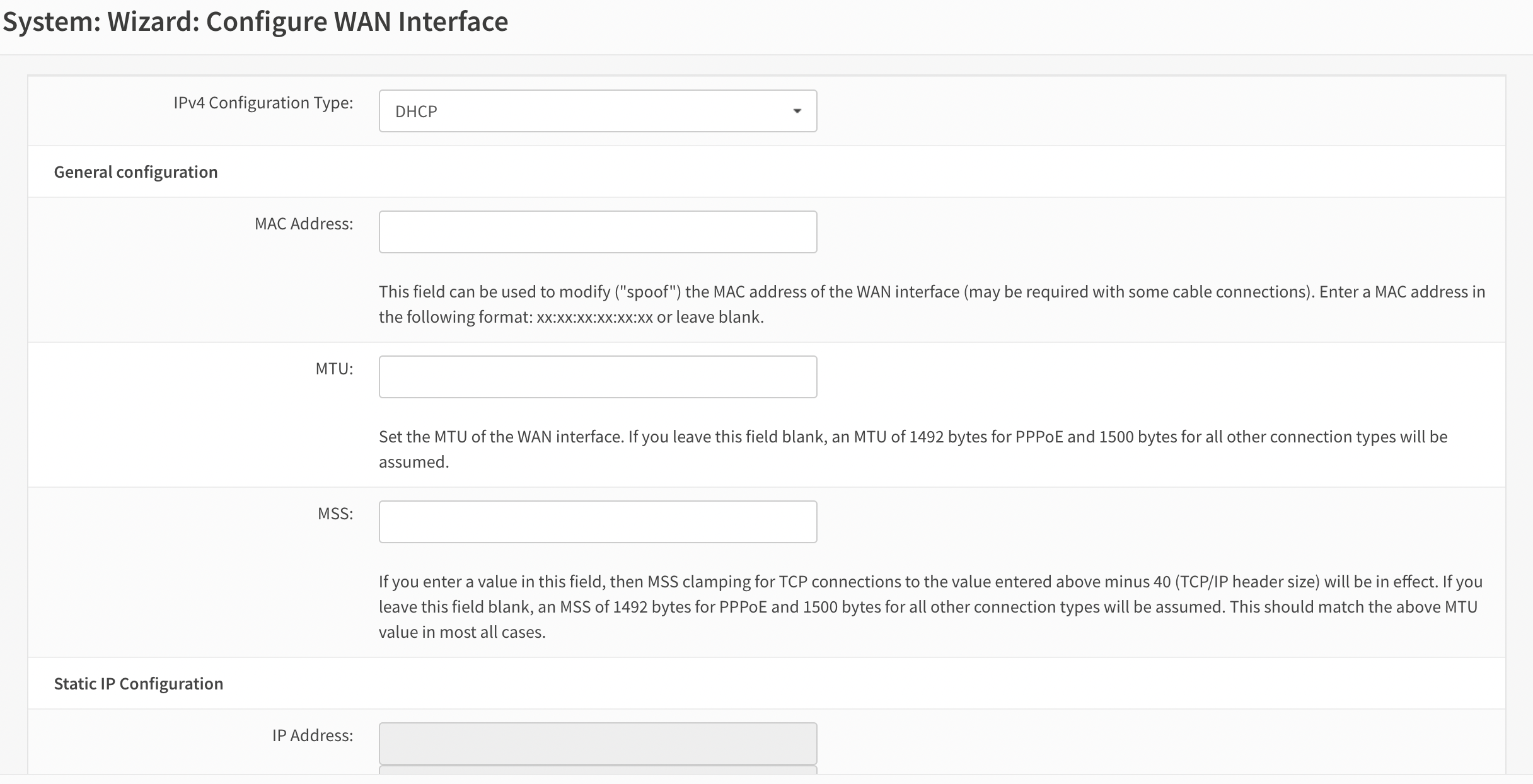
Figure 6. Configure WAN interface
- The next step is to assign an IP address to the LAN interface (see Figure 7).
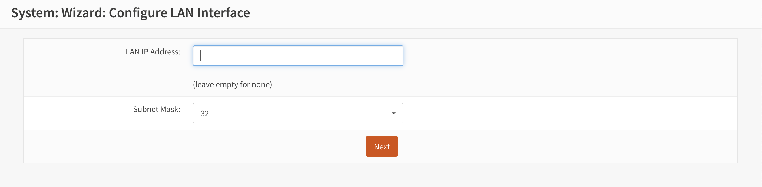
Figure 7. Configure LAN interface
In this case, the IP address will be 10.128.0.10/24. After setting the address, the user should click the “Next” button.
- On the next screen, the user can change the password (see Figure 8).
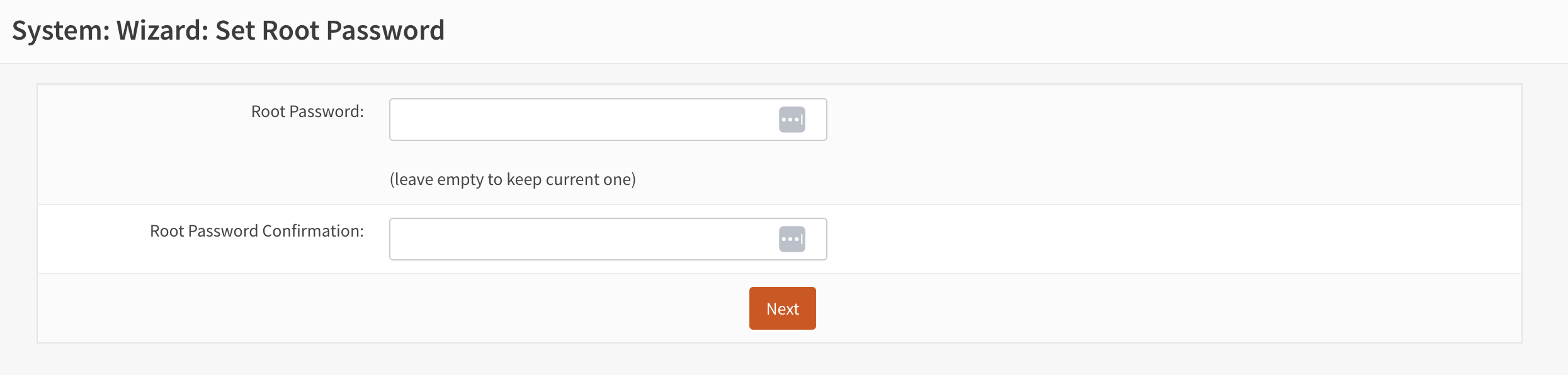
Figure 8. Set root password
After completing these actions it is required to click “Next” and in the next window that appears click the “Reload” button (see Figure 9).
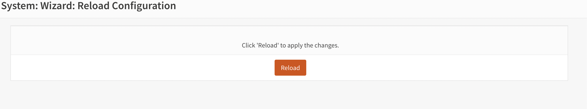
Figure 9. Reload configuration
Wait for the page to reload, then activate the LAN interface by navigating to “Interfaces” and selecting “LAN” (see Figure 10).
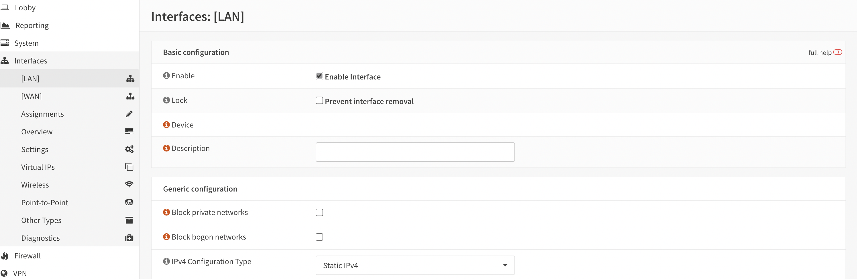
Figure 10. LAN interface
Verify that the IP address is configured correctly, then click the “Save” button.
- Next, configure NAT by navigating to the “Firewall” section, and then selecting “NAT” and “Outbound” (see Figure 11).
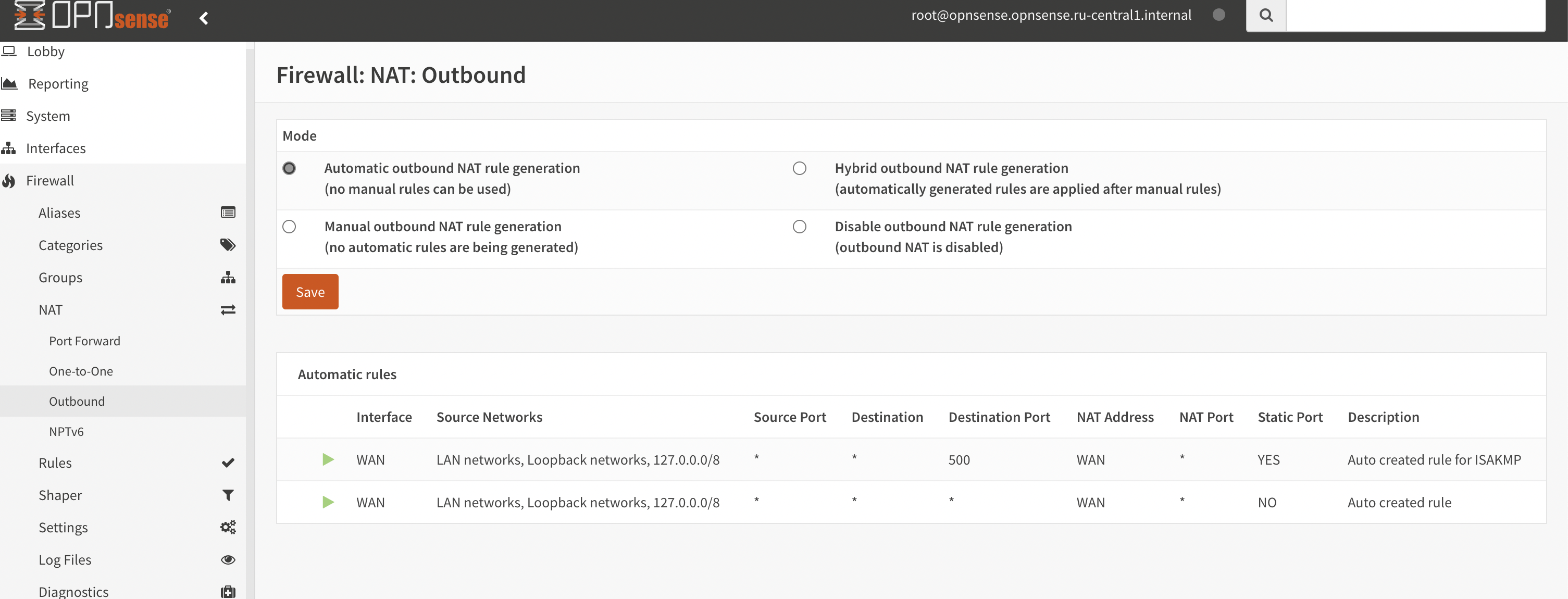
Figure 11. Configure NAT
At this point, the rest of the settings can be left unchanged.
- Adding Floating Rules
To do this, the user needs to open the “Firewall” menu and select “Floating” (see Figure 12).
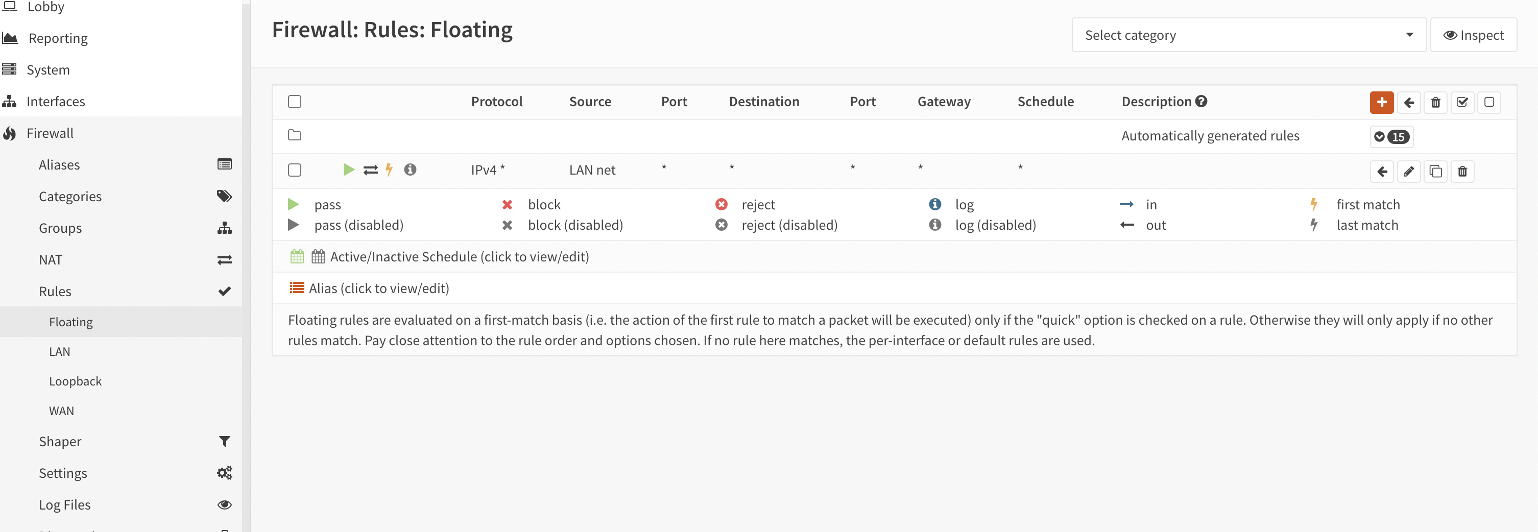
Figure 12. Configure Floating rules
After that, the user can move on to the routing settings in the VK platform.